
A CAD drawing consists of a number of entities (a CAD term for an object in a drawing) sorted in different layers. A help text will appear telling you which specific layer an entity belongs to when you hover the mouse pointer over the entity.
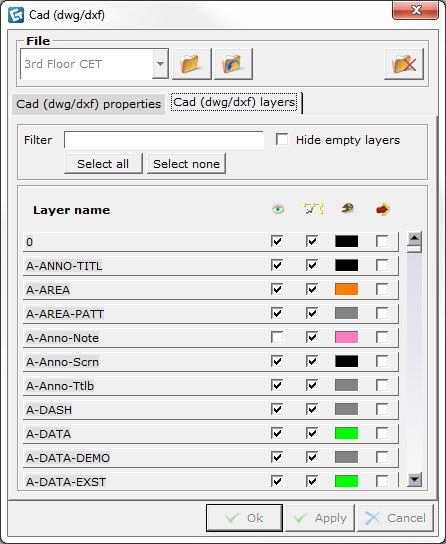
Right-clicking an imported dwg/dxf drawing and selecting CAD (dwg/dxf) layers will open the dialog box with the same name (see Figure 1). Here you will find a list of all the layers in the imported CAD drawing. From this dialog box you can also make further changes to the layers.

Figure 1
The dialog box CAD (dwg/dxf) dialog box has five different columns. Click the links to read more about each column:
At the top of the dialog box, two more options can be found allowing you to filter drawing information and to show/hide empty layers. Selecting the Hide empty layers check box means that you hide all the layers that lack entities.
Note:
|
The Layer Name column shows a list of all layers in the imported drawing.
It is possible to turn off or hide layers in the drawing area. In the Show column, you can choose whether the layer should be displayed or not by selecting or deselecting the check box.
In order for CET Designer objects (lines, dimensions, drawing aids etc.) not to snap to the CAD drawing's entities, it is necessary to deactivate the Snap feature for each layer by deselecting the relevant check boxes.
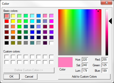
Each specific layer has its own color, To change the color, follow these steps:
Click on the color box shown next to the desired layer.
A Color dialog box opens (see Figure 2).
Select the desired color.
Confirm by clicking OK.

Figure 2
Note: The color you select is applied in both 2D and in 3D. |
The option Force will force a certain layer's color to all entities that are in that layer. This means that all entities that previously had their own specific colors will lose them and obtain the layer color instead.