

Before beginning to use CET Designer, it is a good idea to familiarize yourself with the program's user interface (see Figure 1), which is designed to give you a clear overview of the available options. The program window is divided into four major areas:
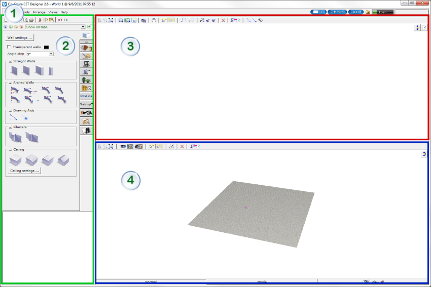
Figure 1:The CET Designer program window.
|
Top area |
The Top area of the CET Designer user interface (see Figure 2) contains the following standard items (starting from top):
Title bar with the current version of software.
Menu bar with the following menus: File, Edit, Tools, Arrange, Views and Help. The upper right corner of the menu bar contains options for accessing the CET Designer Message Center, the Extensions Manager (click the Extensions button), Support, the Control Panel, the system load, and viewing the current price for all products in the drawing area. The price is automatically updated when new products are being placed in the drawing area.
Toolbar with standard program icons.

Figure 2: The Top area of the CET Designer program window.
The Load bar gives you a hint of how heavy your computer is loaded (see Figure 3). Click the bar to access more detailed information.
Figure 3: The load bar
Note: The Load progress bar is only active when you are running the advanced graphics engine, which is turned on in the control panel. |
|
Components area |
The Components area on the left-hand side (see Figure 4) contains the different component tabs. When you move the mouse over the vertical tab bar, a list with the different component tabs is displayed. A tab with an ellipsis icon is a continuation of the same group in the previous tab. Selected component tab is displayed in a lighter color than the other tabs.
When selecting a component in the component tab, it will appear in 2D or 3D in the preview rendering view below (see bottom section of Figure 3). The component in the view can be animated by clicking the rotating arrow button in the top-left corner (see Figure 4 below). You can also select in which dimension the object should be displayed by clicking either 2D or 3D button in the top-right corner of the view
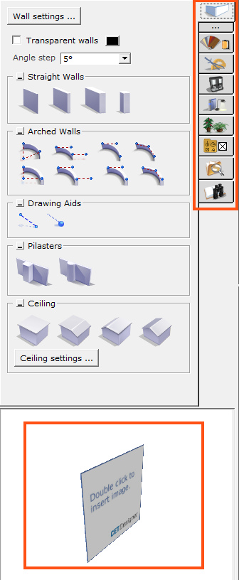
Figure 4: The Components area of the CET Designer program window.
|
2D view of the drawing area |
The top half of the program window is the 2D view of the drawing area (see Figure 5). Use the toolbar to perform different zoom actions, navigate with the camera and to align components.
In the top right corner of the 2D view area, you can choose to view the whole drawing area in 2D, by clicking the Switch to single 2D view icon. To open the paper view, click on the icon Switch to paper view.
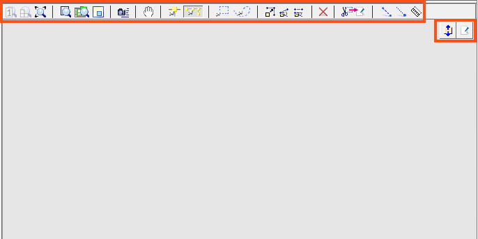
Figure 5: 2D view of the drawing area.
|
3D view of the drawing area |
The bottom half of the program window is the 3D view of the drawing area (see Figure 6). Use the toolbar to perform different zoom actions, navigate, render and more.
In the top right corner of the 3D view area, you can choose to view the whole drawing area in 3D, clicking the Switch to single 3D view icon.
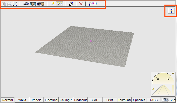
Figure 6: The 3D view of the drawing area.
The navigation bar (Figure 7) enables you to perform camera and zoom actions.
Figure 7: The navigation bar.
Use the View buttons (Figure 8) to switch between different viewing modes, i.e. to determine what objects to display in the 3D view.
![]()
Figure 8: Buttons for various View modes.