If you want more exact component positioning in the CET Designer drawing area, you can use the tools Position, 3 point rotation or 4 point rotation.
To align two components, follow these steps:
In the drawing area, place the two components a short distance from each other.
Go to the Edit menu and select Position, or click the Position icon ![]() on the 2D view toolbar.
on the 2D view toolbar.
Move the mouse pointer to the drawing area. A circle follows.
Move the circle to the first component. The component is marked with a blue rectangle, and the circle finds ("attaches to") certain selected points (see Figure 1).
Click when the circle marks the corner you want to move the other component to. An arrow follows the mouse pointer (see Figure 2).
Move the arrow to the other component. The arrow finds certain selected points.
Click when the arrow is pointing towards the desired corner of the other component.
The two components are attached and aligned.
An input box appears automatically when the Position feature is selected. Here you can indicate exact values for the angles, and X, Y and Z. At the bottom of the box you can also choose if components are to be attached (snapped together) after they have been aligned.
|
Example 1 |
||
|
|
|
|
|
Figure 1 |
Figure 2 |
Figure 3 |
The 3 point rotation feature can be very useful when, for example, you want to specify a custom rotation point and a very precise rotation angle. (see Example 2).
To rotate a component, follow these steps:
Click the 3 point rotation tool ![]() on the 2D view toolbar.
on the 2D view toolbar.
Move the mouse pointer to the drawing area and the component that you wish to rotate.
A blue circle finds ("attaches to") certain suggested rotation points.
Left-click once to select a suitable rotation point. The blue circle remains in position.
Move the mouse pointer to align the line along the component. Left-click once to specify the end point.
Move the mouse pointer to set the rotation angle. You can also type a value in the input box in the upper right corner of the drawing area.
Left-click once and the component rotates according to the specified angle.
|
Example 2 |
|||
|
|
|
|
|
|
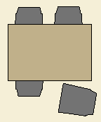
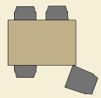
Figure 4 One chair is not properly aligned with the table. |
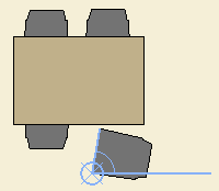
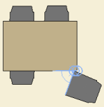
Figure 5 The circle marks the rotation point and the angle shows the rotation. |
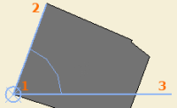
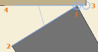
Figure 6, close-up 1) Select rotation point. 2) Align the first line with the component. 3) Set the rotation angle. |
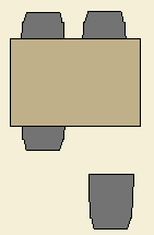
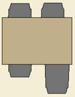
Figure 7 After rotation, the chair has the proper angle and can easily be moved closer to the table. |
|
Tip!
|
The 4 point rotation feature can be very useful when, for example, you want to specify a custom rotation point and a very precise rotation angle (see Example 3). Apply this feature when, for example, aligning a component with a help line as it enables you to align a component with another object, called a reference object below.
To rotate and align a component, follow these steps:
In the drawing area, place two components a short distance from each other.
Click the 4 point rotation tool ![]() on the 2D view toolbar.
on the 2D view toolbar.
Move the mouse pointer to the drawing area and the component that you wish to rotate.
A blue circle finds ("attaches to") certain suggested rotation points.
Left-click once to select a suitable rotation point. The blue circle remains in position.
Move the mouse pointer to align the line along the component. Left-click once to specify the end point.
Move the mouse pointer to the reference object.
A blue circle finds ("attaches to") certain suggested reference points.
Left-click once to select a suitable reference point. The blue circle remains in position.
Move the mouse pointer to specify the angle for rotation. You can also type a value in the input box in the upper right corner of the drawing area.
Left-click once and the component rotates and aligns with the reference object.
|
Example 3 |
|||
|
|
|
|
|
|
Figure 9 One of four chairs is not properly aligned with the table. |
Figure 10 The circles mark the rotation and reference points and the angle shows the rotation. |
Figure 11, close-up 1) Select rotation point. 2) Align the first line with the component. 3) Select reference point. 4) Align the second line with the reference object. |
Figure 12 After rotation, the chair has the proper angle and has been aligned with the table. |
|
Tip!
|