
When
you start the Reconfiguration Tool, a basic pre-made flowchart is
displayed, see Figure 1 below. This graphical representation is made
up of blocks and arrows. Each block has an item count showing exactly
how many items it contains. Blocks can be renamed to represent what
the block contains, and you can change color of all types of blocks.
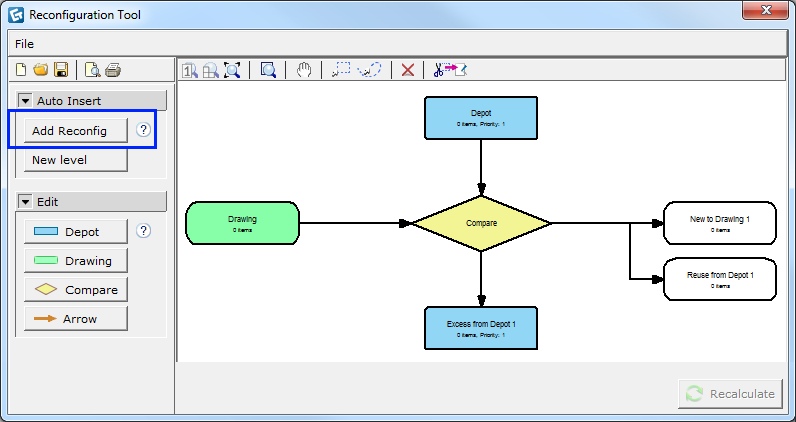
Figure 1: The pre-made flowchart
is inserted when you click the Add reconfig button.
Note
|
A Depot block contains existing items that can be reused in your project drawing. A reconfiguration can consist of one or several depots. Depots can be drawings or PM SIF files. Each file is loaded by double-clicking on the depot block or right-clicking and selecting Load file. You can also drag and drop a file onto the depot block. Each depot displays a priority order to show from which depot items are pulled first, second and so on. Items that are not used in the drawing are placed in Excess from Depot for later use.
To add existing items, follow these steps:
Double-click on the depot block or right-click and select Load file. You can also drag and drop a file onto the depot.
Browse for a file with existing products, either a CET Designer drawing or a PM SIF file; select it and click Open.
Rename
the depot in the green edit box to represent what the block contains.
Note: a shorter label will
make printing easier.
Here you can also set the priority order (see explanation below) and
change the color of the block.
After
loading the file, select the depot block to view a list of all items
in the calculation view below the reconfiguration chart. You can change
the settings of the article view by clicking the View
settings button.
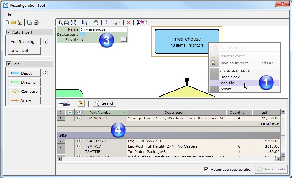
Figure 3: A selected Depot block
with belonging article view.
The rules for the priority order of the depot blocks are the following:
Set priority; from 1 (highest prio) to 10 (lowest prio).
Alphabetical; if two or more depot blocks have the same priority, the Reconfiguration Tool pulls items from them in alphabetical order.
Horizontal position; items are pulled from depots from left to right.
Vertical position; items are pulled from depots in a descending order.
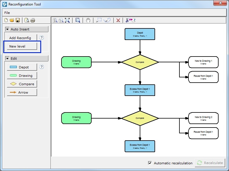
A Drawing block contains a project drawing file, either a CET Designer drawing or a PM SIF file, which is loaded by double-clicking on the drawing block or right-clicking and selecting Load file. You can also drag and drop a file onto the drawing block. A reconfiguration can consist of several drawing blocks on different levels, but each level can only have one drawing, connected to one compare block.
To add a drawing, follow these steps:
Double-click on the drawing block or right-click and select Load file. You can also drag and drop a file onto the drawing.
Browse for a file with new products, either a CET Designer drawing or a PM SIF file; select it and click Open.
Rename the drawing block in the green edit box to represent what the block contains. Note: a shorter label will make printing easier.
After
loading the file, select the drawing block to view a list of all items
in the calculation view below the reconfiguration chart. You can change
the settings of the article view by clicking the View
settings button.
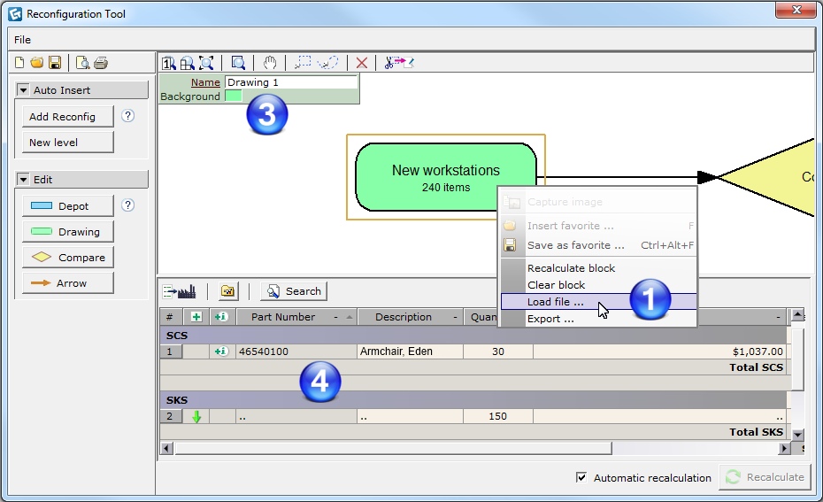
Figure 4: A selected Drawing block
with belonging article view.
The Compare block makes a comparison between a drawing and one or more depots in your reconfiguration. A reconfiguration can consist of one or several compare blocks, but note that only one drawing block can be attached to each compare block.
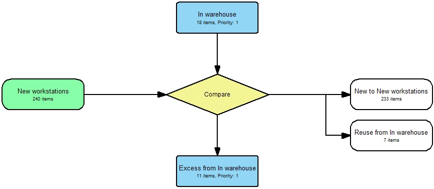
Figure 5: A basic reconfiguration chart
with one Compare block.
For each compare, three types of output blocks are automatically placed:
New to...
Reuse from... (one for each depot)
Excess from...
Output blocks will include the label from the block they are referring to, as in the example New to New workstations, where New workstations is the name of the drawing block.
Blocks are connected to each other with arrows, which symbolize the flow between drawings, depots, and compares. Arrows are automatically added to output blocks. There are built-in rules for how the blocks can be connected to each other, and if you try to link them together incorrectly, the Reconfiguration Tool will give you feedback about this, see Figure 6 below.
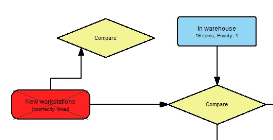
Figure 6: Reconfiguration Tool gives
you feedback if the blocks are incorrectly linked.