
In the Camera tab, you control the camera position and the contents of an image. Here you will also find some advanced settings. From here, you can also initiate a 3D walkthrough.
In the Position Settings field on the Camera tab there are two sliders that enable you to adjust the position of the camera - Camera height and Target height. These two settings together determine the vertical angle of the camera. For example, if the camera height is set to 15,000 millimeters and the target height to 1,000 mm, the image will be taken from almost directly above the target.
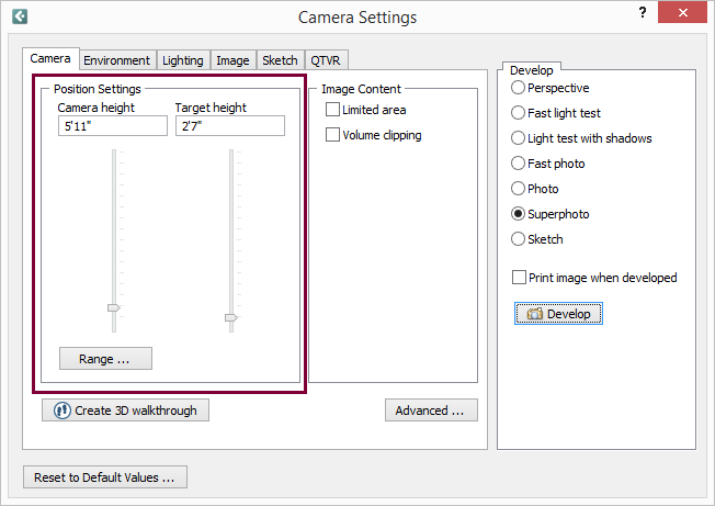
Figure 1 - Position Settings field on the Camera tab
Note:
|
Using the Camera height slider, you can set the height of the camera. When you open the Camera Settings dialog, the default setting is 1800 mm. This could represent a person of normal height taking a picture. By dragging the Camera height slider, or by entering the height you want in the text box, you can set the height of the camera anywhere between 0 and 17,000 mm.
Example:
If you want to take an image from a height of 5,000 millimeters, follow these instructions:
Position the camera in the drawing area.
Double-click on the camera. The Camera Settings dialog is displayed.
In the Camera tab, drag the Camera height slider to a height of five meters or enter 5,000 mm in the text box.
In the Develop field to the right, choose a developing option and click on the Develop button below.
Using the Target height slider, you can specify the height of the camera's focus. For example, if you are photographing a table, the appropriate target height is around 1,000 millimeters.
Below the Camera height and Target height settings, you will also find a Range button. If you want to change the maximum and/or minimum height for the camera, click on the Range button to open the Range Settings dialog. What you enter here determines the maximum and minimum height for the Camera height and the Target height.
Example:
If you want to photograph an object from a height of 20,000 millimeters, follow these instructions:
Position the camera in the drawing area.
Double-click on the camera. The Camera Settings dialog is displayed.
Click on Range. The Range Settings dialog is displayed.
Enter 20,000 mm in the Max field and click on OK or Apply.
Drag the Camera height slider to its highest point.
Choose a developing option and click on the Develop button in the bottom right-hand corner of the dialog.
It can be difficult to position the camera correctly and produce a good image in a small space. Using either Limited area or Volume clipping in the Image Content field (see figure 1), you can move out the walls and other components that you do not want in your picture.
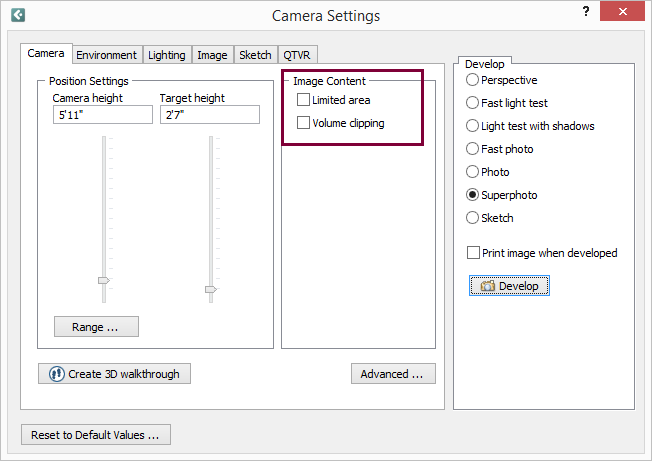
Figure 2 - Image Content field
If the check box Limited area is checked, a rectangular stretchable area is created . Everything within this area will appear in the developed image. Even if only part of a component, for example the corner of a table, is in the limited area, the whole table will appear on the image.
If you want to use the Limited area check box, follow the instructions below:
Select the camera from the Tools tab. Position the camera in the drawing area and aim it by dragging the target to the area or the object which you want to photograph.
Double-click anywhere on the camera, except on the snap points. The Camera Settings dialog is displayed.
Click on the Image Content tab and select Limited area. A rectangle with dashed lines and a number of yellow snap points appears. The rectangle with the dashed lines is the limited area.
The components and the environment in the limited area now appear in the Camera View. You can also develop an image so that you can see the area, by clicking on Develop on the right-hand side of the Camera Settings dialog.
You can stretch, shrink, move and rotate the limited area. You can also move the target within the limited area.
To do this, follow the instructions below:
To stretch or shrink the limited area, click on one of the snap points on the side of the rectangle, hold down the mouse button and drag the area in the direction you want.
To rotate the limited area, click on one of the snap points on the corner of the rectangle, hold down the mouse button and drag the area in the direction you want it to move.
You can move the whole limited area by clicking on the activated target and dragging it in the direction in which you want the area to move to. The camera will follow.
You can also move the focus point within the limited area. To do this, follow the instructions below:
Deactivate the target's snap point by clicking on it. The snap point will change color to gray.
Put the mouse pointer on the deactivated snap point, and click and hold the mouse button.
Drag the target to the position within the limited area where you want it to be.
Using Volume clipping, you can create a restricted area within the wide angle (only the components within this area will appear in the developed image. This means that only that part of a component which is inside the volume clipping area will be visible.
If you want to use the Volume clipping check box, follow the instructions below:
Select the camera from the Tools tab. Position the camera in the drawing area and aim it by dragging the target to the area or the object which you want to photograph.
Double-click anywhere on the camera, except on the snap points. The Camera Settings dialog is displayed.
Click on the Image content tab and click on Volume clipping. The volume clipping area appears as two dashed lines within the camera's wide angle. The snap points on the volume clipping area are gray (deactivated).
Drag the lines of the volume clipping area to a position where they enclose the area which you want to appear in the image.
Activate the volume clipping area by clicking on the gray deactivated snap points.
Click on Develop on the right-hand side of the Camera Settings dialog.
Note:
|
On the Camera tab in the Camera Settings dialog, there is an Advanced button. From here you can open the Advanced Camera Settings dialog. In this dialog, you can e.g. check the options in the Transparency field if you want to develop transparent 3D images. These options can be used, for example, together with the Perspective developing option to show something not visible in a normal 3D image.
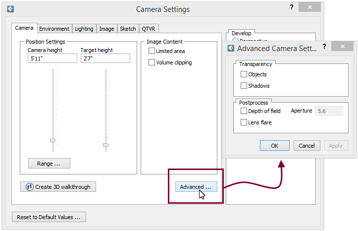
Figure 3 - Advanced Camera Settings dialog
Example:
You want to be able to see components which are in another room. You want to be able to see through a wall.
To do this, follow the instructions below:
Click on the Advanced button on the tab Camera.
In the Advanced Camera Settings dialog, check the box Transparent.
Click on OK or Apply.
In the Develop field in the Camera Settings dialog, click on the button Develop.
In the Postprocess field, you can postprocess 3D images using either of the two methods Depth of field or Lens flare. The different alternatives, combined or on their own, give the developed 3D image an authentic feeling.
Note:
|
Depth of field makes the focal point of the camera coincide with the object that the camera's target point is placed on. With depth of field checked the field Aperture is activated and you can choose the aperture of the camera. Figure 1 is made without depth of field with the target point placed on the front chair. In Figure 2, the depth of field is chosen. The target point is on the front chair and aperture is set to 1.8.
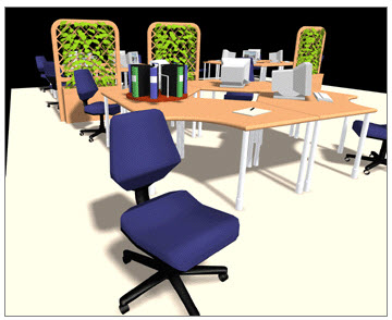
Figure 4
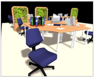
Figure 5
With Lens flare checked, the light sources you might have placed on the drawing area will give reflections on the developed 3D image. Figure 3 is made without lens flare and Figure 4 with lens flare.
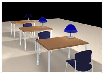
Figure 6
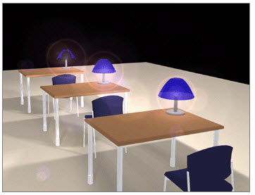
Figure 7