
The top row of components on the Line Drawing 1 tab is called Drawing Aids and consists of five components. Drawing Aids are, as their name suggest, tools to help you when you are creating a drawing. The drawing aids do not appear on printouts.

The different drawing aids are used for different purposes:
The Reference point is an artificial snap point. You fix other line drawing components to it.
The Multiple reference points component is used to create a number of reference points one after another.
The Help line is used, for example, to create intersections or a network of coordinates in the drawing area.
The Multiple help lines component is used to draw several help lines one after another.
The Reference point on arc is used in the same way as the standard reference point, but on arcs.
You want to put a reference point on an existing line, 1,000 mm from the end of the line.
Follow the instructions below:
Draw a line.
Select the component Reference point.
Move the cursor to the end of the line. The help text End is displayed and the reference point snaps to the end of the line.
Click with the mouse. The input display for the reference point is shown automatically.
In the input display, enter the distance from the end of the line to the reference point, 1,000 mm, in the field Length.
Move the cursor towards the wall to align the reference point until it snaps to the line.
Click the reference point in its final position. You can now see the blue reference point in the drawing area.
Example 2: Multiple reference points
You want to use two reference points to position a window which is 1,000 mm wide in a wall. The distance between the end of the wall and the window is 200 mm.
Follow the instructions below:
Draw a line.
Select the component Multiple reference points.
Move the cursor to the end of the line. A help text that says End appears and the reference point snaps to the line.
Click the reference point in position.
In the input display, enter the distance from the end of the line to the first reference point, 200 mm, in the field Length.
Move the cursor towards the wall to align the reference point until it snaps to the line.
Click with the mouse. You can now see the first blue reference point in the drawing area.
The input display is still available, which means that you must enter the next value, that is 1,000 mm, which is the length of the window.
Move the cursor towards the wall to align the reference point until it snaps to the line.
Click with the mouse. The next reference point is now visible in the drawing area. You can now position a window between the two points.
You want to extend a help line from the middle point of an existing line.
Follow the instructions below:
Draw a line.
Select the component Help line.
Move the cursor to the middle of the line. A help text that says Middle appears and the help line snaps to the line.
Click the help line in position.
Drag the help line until it is the length you want, without holding the mouse button down.
Click the help line in its final position.
Example 4: Multiple help lines
You want to use several help lines one after another to create a simple network of coordinates.
Follow the instructions below:
Select the component Multiple help lines.
Click the component in position on the drawing area.
Drag the help line until it is the length you want.
Click with the mouse.
Continue to drag the cursor in the direction you want. A new help line appears.
Click when the line is the length you want.
Continue to follow these steps until you have as many help lines as you want.
Example 5: Reference point on arc
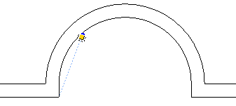
You want to create a window in a bay. The wall of the bay is in the shape of an arc, which can make measuring difficult. However, you have made a straight dimension from the corner to the window, that is, not alongside the curved walls. The dimension is 800 mm on each side.
Follow the instructions below, to measure up the position of the window:
Select the component Reference point on arc and click it in position where you measured from. The input display is shown.
Drag the cursor along the curved wall to determine where the snap point should go.
There are three fields in the input display: Arc angle, Arc length and Chord length. Move to the Chord length field, using the Tab key.
Enter the dimension: 800 mm.
Click with the mouse. The first blue reference point appears.
Move the cursor to the next corner.
Click the component in position in the other corner. The input display is shown.
Drag the cursor along the curved wall to determine where the snap point should go.
In the input display, move to the Chord length field, using the Tab key.
Enter the dimension: 800 mm.
Click with the mouse. The second blue reference point appears.

Figure 1
For more information on positioning a window, see the topic Windows.
|
Note:
|