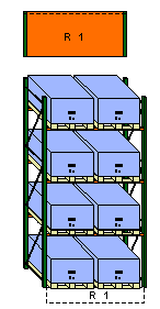

Elevation views are references to the 2D (plan view) components and are used for showing the components from the front. It is not until the elevation is added, that the product can be viewed in 3D and appears in the Calculation. Adding the elevation will also enable you to modify the load height, the number of beam levels etc.
Racks for example, come in different heights and have different arrangements of beams. In order to, for example, change the number of beams of a bay, it has to be visualized in another view than the plan view. When adding an Elevation view to a Bay component in the drawing area, uprights and beams are automatically added to the bay. From this point, you can add or remove beams from the rack or adjust its height.
In the drawing area, the 2D component as well as the elevation receive a number (see Figure 1). The elevation is now known as a “Reference”.

Figure 1
|
Note:
|
When working with components that have elevation views, follow these steps:
First take out the 2D component from the toolbox.
Then place and add the elevation view.
Example:
You want to position a single bay with an elevation in the drawing area.
![]()
![]()
Figure 1 Figure 2
To position the bay follow the instructions below:
On the InstantPlanner main tab, click on the Selective Pallet Racks tab.
Select the Bay component by clicking on it (see Figure 1). Release the mouse button.
Move the component onto the drawing area without holding down the mouse button.
Click in the drawing area to drop the bay in the desired position.
In this example you only want one bay, so move the mouse pointer outside the drawing area or press the Escape key to release the new bay that appears automatically.
Back on the component tab, select the Elevation component by clicking on it (see Figure 2).
Move the component onto the drawing area.
Move the mouse pointer close to the bay in the drawing area until it snaps. Click to add the Elevation.
Move the mouse pointer outside the drawing area or press the Escape key to release the new elevation that appears automatically. In the drawing area, you now have one bay with an elevation (see Figure 3).

Figure 3
|
Note: |
After the elevation is positioned in the drawing area, you can easily remove any of its accessories (pallets, beams etc.).
Follow the instructions below:
Activate the elevation by clicking on it.
Click on the yellow triangular snap point of the accessory you would like to remove (pallet, beam etc.).
Once the elevation is positioned in the drawing area, it is possible to change the height of the upright.
Follow the instructions below:
Activate the elevation by clicking on it.
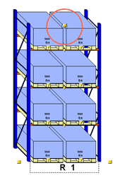
Click and hold the snap points at the top of the elevation (see Figure 4).
Drag the elevation (i.e. the upright) until it is the height you want. A yellow display appears (see Figure 5) which shows how the Height changes as you drag.

Figure 4

Figure 5
|
Note:
|