
A Cad drawing consists of a number of entities sorted in different layers. If you use the mouse pointer to point at a drawing entity (Cad term for an object in the drawing), a help text will generally appear telling you what specific layer that entity belongs to. In order for help texts to be shown also for larger entities, it might be necessary to first explode the entity.
Clicking on the Drawing Data button on the Import and Export tab will open the dialog Imported Cad Drawing Data (see Figure 1 below) with its two tabs - Layers and Advanced.
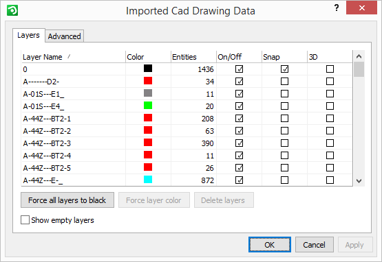
Figure 1: The Drawing Data dialog.
On the Layers tab you will find a list of all the layers in the imported Cad drawing. From here you can also make further changes to the layers.
The tab contains six different columns:
At the bottom of the dialog box three more options can be found allowing you to show/hide empty layers, remove layers and to force a certain layer's color to all entities that are in that layer.
|
Note:
|
The Layer Name column shows a list of all layers in the imported drawing.
After the layer name, the color of each specific layer is also shown in this column. Here you can change the color of one or several layers at the same time.
To change the color of one layer, proceed as follows:
Click on the color box shown next to the desired layer.
The Material/Color Change dialog box opens.
Select the desired color model/type.
Confirm with OK.
If you wish to change the color of several or all layers at the same time (i.e. you would like to have the whole imported drawing displayed in the same color), select the desired layers using Shift and follow the same instructions as above.
|
Note:
|
The next column (Entities), shows how many entities (parts) each layer contains.
It is possible to turn off or hide layers in the drawing area. In the On/Off column, you can choose whether the layer should be displayed or not by checking/un-checking the box.
In order to allow InstantPlanner objects (lines, dimensions, drawing aids etc.) to snap to the Cad drawing's entities, it is necessary to activate the Snap feature.
|
Note:
|
In the last column (3D), you can determine whether the layer entities should be displayed in 3D or not.
Leaving the Show empty layers box empty means that you hide all the layers that lack entities.
Using the Delete layers button, you delete all the layers (and their entities) that are selected in the column above.
|
Note:
|
The option Force Layer Color will force a certain layer's color to all entities that are in that layer. This means that all entities that previously had their own specific colors will lose them and obtain the layer color instead.
On the Advanced tab you will find two main fields - Purge, Visualization and Draw order. All options available on this tab give control of the imported Cad drawings and allow you to improve the redrawing speed and to reduce the memory usage.
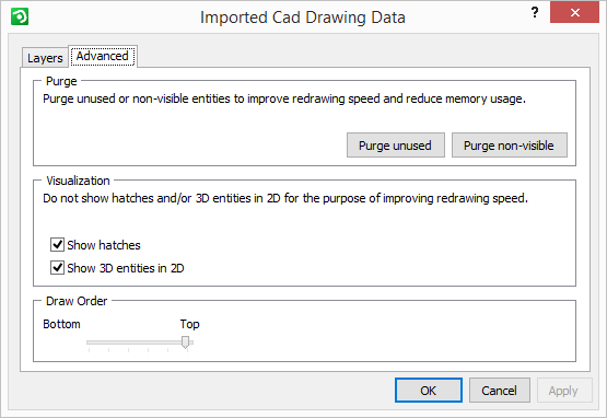
When selecting Purge unused, you delete drawing data that is not being used. When selecting Purge non-visible, you delete layers that are turned off.
Unchecking the Show hatches option will give you a less detailed 2D representation in the drawing area by not showing hatches (hatch = filled patterns). Unchecking the option Show 3D entities in 2D will turn off all 3D entities in the 2D representation in the drawing area.
Drag the Draw order slider to determine the order in which the Cad entities should be drawn. By dragging the slider to the maximum level, the Cad entities will end up on top of all other components. By dragging it to the lowest level, they will be shown beneath other components.