

The top five components are drawing aids, which also appear on the tab Line Drawing 1. However, as these components can be very helpful in positioning windows and doors, they are also accessed from the tab House Components.
Before you start positioning doors and windows on your layout drawings, it is a good idea to first pre-set the values that at are known. You do this in the Defaults dialog, accessed by clicking on the Defaults button at the top of the House Components tab. These settings will only apply to components which have not yet been positioned in the drawing area.
The Defaults dialog has three main tabs: Door, Window and General. At the bottom of the dialog is a Reset to Default Values button where at any stage, you can reset the dialog to the default values.
On the Door tab, you pre-set values for doors. The tab has three fields: General, Outer Frame Width and Rollgate.
In the General field, you pre-set the door's Height and Thickness.
In the Type drop-down list, you can choose between Standard, Rectangular opening, Panels and Glass panels. Standard is a normal door, and Rectangular opening is an opening without a door or doorcase. Panels and Glass Panels means a door with a number of inset panels, the latter having glass panels.
In the Handle list box there are four different choices: Standard, De Luxe, Knob and None.
In the Doorstep check box, you can choose whether or not to have a doorstep.
In the Outer Frame Width field, in the At door box, you can choose the thickness of the frame around the door, as seen from in front (the direction in which the door opens).
In the Behind door text box, you can enter the thickness of the doorcase against which the door closes. This is the surround which stops the door when you close it. In Figure 1, the frame width of the left door At door is 10 mm and Behind door 20 mm. For the door to the right, the frame thickness At door is 50 mm and Behind door 75 mm.
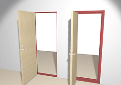
Figure 1
In the Rollgate field, you enter a percentage to indicate how far open the Rollgate component should be, when it is shown in 3D.
On the Window tab, you pre-set values for windows. The tab has three sub-tabs: General, Frame and Details.
General
The General tab contains three fields: 3D, Straight Window and Curved Window.
In the 3D field, you can pre-set the Height of the window and the Distance to floor (the distance between the floor and the lower edge of the window).
Straight Window
In the Straight Window field, you can pre-set the Depth of the Straight window component.
In the Type drop-down list, you can choose the type of window to use: Elliptical, Divided or Rectangular opening. Rectangular opening is an opening without a window.
Curved Window
In the Curved Window field, you can pre-set the Depth of the Curved window component. In the Type drop-down list, there is only one type of window to use, Divided.
The Frame tab has two fields: Outer Frame Width and Inner Angle of Outer Frame.
Outer Frame Width
In the Outer Frame Width field, you can enter the width of the outer gray frame of the window. In the Side box, you enter the width of the sides of the frame. In the Top and Bottom boxes, you enter the width of the top and bottom parts of the frame respectively. In Figure 2, all the frame dimensions for the left window are set to 50 mm. For the right window, all the frame dimensions are set to 100 mm.
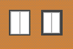
Figure 2
Inner Angle of Outer Frame (°)
In the field Inner Angle of Outer Frame (°), you can determine the outer frames inner angles. If you specify these angles, the window will open further outwards than it does inwards (Figure 3).
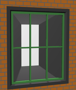
Figure 3
The Details tab contains three fields: Inner Frame, Number of Divisions and Divider Width.
In the Inner Frame field, you enter the dimensions for the window's inner white (light gray on the picture) frame.
In the Width box, you enter the width of the inner frame. In Figure 4, the width of the left windows inner frames is 30 mm. The width of the right windows inner frames is 100 mm.
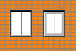
Figure 4
In the Depth box, you enter the depth of the inner frame. In Figure 5, the depth of the inner frame for the left window are 30 mm. The depth of the inner frame for the right window are 100 mm.
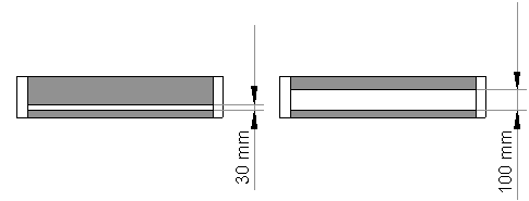
Figure 5
In the Edge depth box, you can choose how far the white frame extends into the outer, gray frame. In Figure 6 the edge depth for the left window is 35 mm and 120 mm for the right window.
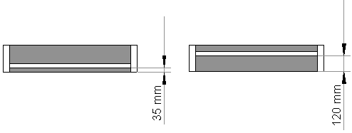
Figure 6
In the Number of Divisions field, you specify the number of vertical and horizontal divisions that the windows should have. If you want a window without divisions, you enter 1 in the Horizontal box and 1 in the Vertical box. A simpler way is to work out how many panes you want to have. If you enter 2 in the Horizontal box, and 3 in the Vertical box, you will have 2 × 3 = 6 panes (the left window in Figure 7). If you enter 4 in the Horizontal box and 4 in the Vertical box, you will have 4 × 4 = 16 panes (the right window in Figure 7).
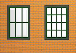
Figure 7
Divider Width is the width of the window bars. You can enter the width of the horizontal and vertical bars.
On the General tab, there are two different fields - Simple Lines and Printout.
The Simple Lines field contains two drop-down lists: Line type and Width. In the Line type list box, you can choose the type of line used to outline doors and windows in the drawing area. In the Width box, you can choose the width of the line.
If you would like drawing aids to appear on the printout, check the box Show drawing aids on printout in the Printout field.
When you have made the desired settings, always confirm with OK or Apply.