
The Level tool is used for adding one or several floors to the ground level. You can also determine the height from the ground for each level.
In order to add one extra level to the ground level, proceed as follows:
Select the Level tool from the Tools tab.
Move the mouse pointer to the drawing area. A small, gray square-shaped frame is attached to the mouse pointer.
Place the level in the drawing area and adjust its size in one step by clicking and holding the mouse button. Then move the mouse pointer in a diagonal direction until you have stretched the frame to desired size.
Release the mouse button. The Level Settings dialog appears (see Figure 1).
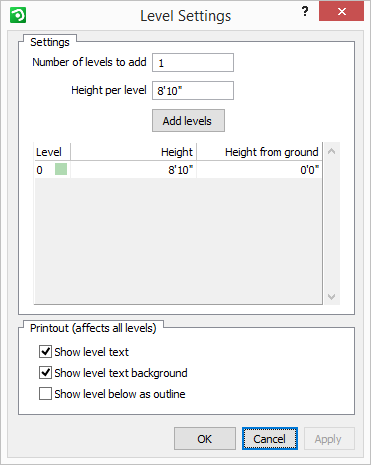
Figure 1: the level settings.
Move the mouse pointer outside the drawing area to drop the level and then go to the dialog.
Since you are to add only one extra level and this amount is already predefined in the text field next to the heading Number of levels to add, there is no need to make any alterations.
Instead go to the text field below and enter the Height per level, i.e. the height difference between the levels.
Click once on the Add levels button. The extra level is shown in the table below.
Click OK or Apply. The extra level is now also visible on the drawing area, above the gray frame that represents your ground level. The two levels are linked together and each has a green label attached to it, displaying the level status (see Figure 2 below).
Figure 2
The Level Settings dialog also contains the Printout field. Checking the box Show level text... will display the text on the green label on the printout. Checking the box Show level text background... will also display the actual label behind on the printout. This option is only available if you have chosen to display the text. Both options affect all levels in the drawing area.
|
Note:
|
Now it is possible to place components on the different levels. Select the desired components and place them within the gray frames that represent your levels in the drawing area. Within each level, a gray outline is shown. These are contours of the components that are placed in the level closest below.
Each level has a green label attached to it, showing the level status. The following information is displayed:
Height from ground: Shows the value that you typed in.
Show level below as outline: Yes/No
Show 3D together: Yes/No
In order to change the status of a level, click on the yellow triangle in the top left-hand corner of the green label, or right-click on the green label. A pop-up menu appears which displays the following options:
Delete – deletes all levels that are linked together.
Add Another Level – adds a new level above the existing levels. The Level Settings dialog opens and enables you to change values or to add levels.
Copy Line Drawing to Levels Above – copies all line drawing components, for example, a building layout from the ground level and pastes this information to all other levels. The position of the line drawing components will be exactly the same as they were originally.
Reload - is used for redrawing the selected level. If you have made updates to a level and this information does not appear in the drawing area, click here.
Settings - opens the Level Settings dialog.
Show 3D Together – allows you to show/hide part or all of the 3D (three dimensional drawing) for the chosen levels. Turning it off means that in a 3D image, components on different levels will appear on ground level. If the 3D is turned on, the different levels will be shown at the height that you have specified for them (see Figure 3 below). This choice applies to all levels that are linked together.
Figure 3
Show Level Below as Outline – shows/hides the outline of the level below.
|
Note:
|
Figure 4