
Using the Position Components, you can tag components in the drawing area that you would like to specify individually in the quotation. This means that you can create a separate specification for a selected group of components.
In the program, there are three different versions of the same function: Rectangular position, Surface position and Free position. When placing either of the tools in the drawing area, the Position Settings dialog is shown (Figure 1). To the right you will also find the Remove position tool, with which you can exclude groups or components from a specified position.
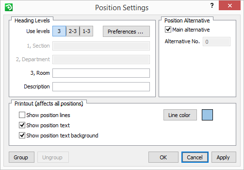
Figure 1: the Position Settings.
 Follow the instructions below, to use the component Rectangular position:
Select the Rectangular position from the Tools tab and move it onto the drawing area. A light-blue square appears next to the mouse pointer.
Move the mouse pointer and the blue square to a group or an individual component for which you want to create a separate specification.
Click the blue square in position, hold down the mouse button and drag the square over the component for which you want to create a separate specification.
Release the mouse button. The component you selected now have shadows. The Position Settings dialog is displayed.
In the Heading Levels field, by the heading Use levels, select the desired heading levels (i.e. specify which ones of the white text boxes below that you would like to use for typing in information).
Enter the information you want visible on the drawing layout and in the quotation on the different levels.
Click on OK or Apply. The blue label that belongs to the position in the drawing area displays the information you entered.
The Position Settings dialog contains a few more advanced options, such as Preferences, Position Alternative and Position Quantity.
At the bottom of the dialog, there are also two buttons: Group and Ungroup.
Using the Preferences button, you open the Position dialog. Here, you can change the title displayed on the different heading levels. Checking the Auto number last box in the same dialog means that the position will be numbered automatically. In the No headings box, you can choose whether you want to have the titles of the heading levels displayed or not. When you have chosen the settings you want in the Position dialog, click on OK or Apply.
In the Position Alternative field, it is possible to uncheck the Main alternative box in the field Position Alternative. You do this if you want to present an alternative to the main quotation.
Checking the box Show position lines... will show the lines that define all positions on the printout. Clicking the Line color button makes it possible to choose the desired color of the lines.
Checking the box Show position text... will show the text that you have entered in the different heading levels above on the printout. The option is valid for all positions on the printout.
Checking the box Show position text background... will show the actual text box on the printout. The option is only valid when you have chosen to display the text, but then for all positions on the printout.
The Group button at the bottom of the Position Settings dialog is used to visually connect the components that form a group. Once clicked then all components in the group will maintain the same position relative to one another, and will move around as a group in the drawing area.
The Ungroup button is used to break this connection so that the components can be moved individually. The components still belong to the same position though. It is possible to add new components to an existing position.
Follow the instructions below:
If necessary, enlarge the light-blue square which delimits the position by clicking on one of its yellow snap points and dragging.
Place the new components inside the light-blue square, thereby adding them to the existing position.
If you have grouped the other components in the room and want subsequently positioned components to be added to the group, do as described below:
Double-click on the position's yellow triangle to open the Position Settings dialog.
Click the button Group. A dashed line shows that the new component is grouped.
To see the entire grouping, click on the room component or one of the components in the room.
|
Note: To be able to Group and Ungroup, the position's blue label has to be activated. Click on the position's yellow triangle to activate it. |
The Surface position is used to enclose components in a looser shape than the Rectangular position which uses a square. When placed on the drawing, it also brings up the Position Settings dialog.
 In order to place the Surface position, follow the instructions below:
Select the Surface position and move it onto the drawing area. A small circle appears next to the mouse pointer.
Move the mouse pointer and the circle to a group or an individual component for which you want to create a separate specification. Click the mouse button.
Move the mouse pointer in any direction you want. A light-blue line appears following the mouse pointer.
Enclose the component or the group using the lines.
When you have enclosed the component with lines, the Position Settings dialog appears. For more information on filling out the dialog, see the previous heading about the Rectangular position.
Using the Free position, you can specify components without enclosing them in a shape. Instead, you choose them one at a time. Follow the instructions below:
Select the Free position and move it onto the drawing area.
Click it in position close to the component or group for which you want to create a separate specification. The Position Settings dialog appears.
Complete the dialog. For more information on filling out the dialog, see the description above about the Rectangular position.
Now you must choose the groups or components which you want to specify. Double-click on the blue position label. Next to the mouse pointer, the text Position No. (together with the text you have entered for that position) appears.
Move the mouse pointer to the new components and groups that are to have the same specification. When the text on the mouse pointer snaps to the components, click on them. The components or groups you selected now receive a shadow, which means that they now belong to the same position. The shadows are only visible when you click on the blue position label on the drawing area.
Using Remove position, you can exclude groups or components from a specified position.
Follow the instructions below:
Select the Remove position tool and move it onto the drawing area.
Snap it onto the component(-s) that you want to exclude from the position.