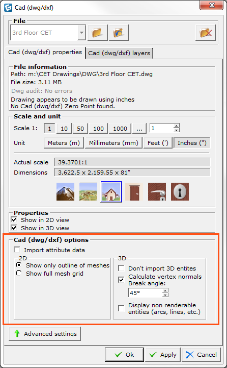

If you wish to have more control of the 2D and 3D presentation of the imported dwg/dxf drawing in CET Designer, click the Advanced settings button in the bottom-left corner of the dialog box Cad (dwg/dxf) Properties.
Under the heading Cad dwg/dxf options (see Figure 1), the following advanced settings are available for:
A. 2D presentation:
Show only outline of meshes - displays a simple outline of the drawing in the 2D view.
Show full mesh grid - displays a detailed drawing with full mesh grid information in the 2D view.
B. 3D presentation:
Calculate vertex normal - smooths out the rough-edged appearance of a multifaceted surface. CET Designer calculates the surface normally and blends the colors across two or more adjacent faces. The break angle is the angle at which CET Designer interprets an edge. The default is 45 degrees. Angles greater than 45 degrees are considered edges. Angles less than 45 degrees are smoothed. To define an edge as less than 45 degrees, reduce the smoothing angle.
Displays non renderable entities (arcs, lines etc. ) - displays non renderable entities as thin cylinders. In the 3D view, CET Designer displays all drawing information as rendered. However, simple lines, arcs and polylines etc. are so called non renderable entities, which means that they are not shown in the 3D view. Selecting this option will display them as thin cylinder lines.

Figure 1 - The Cad (dwg/dxf) Properties dialog