
To draw two-dimensional arcs in CET Designer, go to the Drawing 3D component tab (see Figure 1). Read more below on how to use the different arc types.
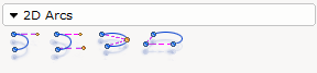
Figure 1
The following arcs are available in the program:
Arc through tangent and angle (also available as a double arc)
Arc inside two tangent lines (also available as a double arc)
Arc through three points (also available as a double arc)
Arc specified by radius and angle
Note: Double arcs function in the same way as single arcs in the drawing area. |
The Arc through tangent and angle is used for drawing a curve as a tangent of a line, that is as a continuation of a line (see Figure 2 below).
Proceed as follows:
Select the arc, snap it to the end of the line and click.
Enter the desired radius in the Radius field in the input box.
Move the mouse pointer horizontally to the right, until the arc's red dashed help line forms an extension of the solid existing line. The entry in the Angle field in the input box should be 0.00.
Click once. Move the mouse pointer downwards so that it is below the level of the horizontal line.
In the input box, the Arc angle field is selected. Enter the desired value and click. The arc is completed (see Figure 2).

Figure 2
The Arc inside two tangent lines is used for drawing a curve between two lines in order to join them (see Figure 3).
Follow the instructions below:
Select the arc and snap it to the upper one of the parallel lines. Click the arc in position.
A red dashed line appears next to the mouse pointer. Make sure that the component's red dashed line forms an extension of the solid existing line and click again.
Move the mouse pointer (the arc will follow it) towards the end of the other line. When the red dashed line snaps to the end of the line and the help text End (see Figure 4) is displayed, click the arc in position on the other line.
Drag the red dashed line out so that it forms an extension of the solid line and click again.
Figure 3
Figure 4
The Arc through three points component is used when three fixing points are given (see example in Figure 5, 6 and 7 below).
For example, if you have drawn something similar to what you see in Figure 5 and would like to add an arched extension similar to the one in Figure 7, follow the instructions below:
In order for there to be three points for the arc to snap to, you must create the middle point using a Help line.
Select the Help line. Move it towards the middle of the solid line on the lower long side. The help line will find the middle of the long side of its own accord.
Click the help line in position when the help text Middle is displayed. Continue to hold down the mouse button and drag the help line to the desired length (Figure 6).
Select the Arc through three points and snap it to the first point. Click the arc in position.
Move the mouse pointer to the middle point, which is the end of the help line. The arc snaps. Click the arc in position (Figure 7).
Move the mouse pointer to the last fixing point and finally click. An arc has been created.
Figure 5 Figure 6 Figure 7
The Arc through radius and angle component is used when you would like to place an arc and the arc angle and radius are given (see Figure 8 below).
For example, you have drawn a rectangle and would like to create a rounding in one of the corners. You know the exact dimensions of the rounding. Follow the instructions below:
Select the Arc through radius and angle component and click it in position the corner of the rectangle, where you are to cut out a piece to create the rounding.
In the input box, enter the desired value in the field Radius.
Snap one of the arc's fixing points on one of the sides of the rectangle (if it has not already snapped there) and click it in position.
Choose the direction of the arc using the mouse and click.
Drag the arc out to the desired degree and click it in position.
Remove the corner piece using the Trim lines tool.
Figure 8