
Under the heading Arcs, there are eight items in total - four different types of arcs and the double versions of these. Below, we will describe the behavior of the single arcs.

The following arcs are available in the program:
Arcs are used to create rounded shapes. Provided that you have pre-set a height for the arcs in the Defaults dialog, they will appear in 3D.
You place arcs in the same way as other line drawing components. You can also stretch the arcs to change the arc angle as well as the radius. It is also possible to change their color in the plan view as well as in 3D.
|
Note:
|
The Arc through tangent and angle is used for drawing a curve as a tangent of a line, that is as a continuation of a line.
There are two ways of positioning this arc - follow one of the sets of instructions below:
A. Using the input display
Example:
You want to complete a horizontal line with a 180 degree clockwise arc with a radius of 1000 mm.
Proceed as follows:
Select the arc and snap it to the end of the line. Click the arc in position.
In the input display, enter 1,000 mm in the field Radius.
Press the Tab key and enter 0 in the field Angle.
Press the Tab key to move to the Clockwise field and enter 'Y' for Yes.
Press Enter. The input display shrinks to show only two fields.
Press the Tab key to move to the Arc angle field and enter 180.
Confirm your entry by pressing Enter again. The arc is completed (see Figure 1).

Figure 1
B. Using the mouse
Example:
You want to complete a horizontal line with a 180 degree clockwise arc, but this time you prefer to work mainly using the mouse.
Follow the instructions below:
Select the arc and snap it to the end of the line. Click the arc in position.
In the input display, enter 1,000 mm in the field Radius.
Move the mouse pointer horizontally to the right, until the arc's red dashed help line forms an extension of the solid existing line. The entry in the Angle field in the input display should be 0.00.
Click once. The input display now contains only the fields Clockwise and Arc angle.
Move the mouse pointer downwards so that it is below the level of the horizontal line and click.
Drag the arc outwards until the entry in the Arc angle field in the input display is 180 degrees and click.
The Arc inside two tangent lines is used for drawing a curve between two lines in order to join them (see Figure 2).
Follow the instructions below:
Select the arc and snap it to the upper one of the parallel lines. Click the arc in position.
A red dashed line appears next to the mouse pointer. Make sure that the component's red dashed line forms an extension of the solid existing line and click again.
Move the mouse pointer (the arc will follow it) towards the end of the other line. When the red dashed line snaps to the end of the line and the help text End (see Figure 3) is displayed, click the arc in position on the other line.
Drag the red dashed line out so that it forms an extension of the solid line and click again.
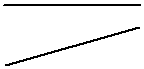
Figure 2
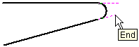
Figure 3
The Arc through radius and angle component is used when arc angle and radius are given.
Example:
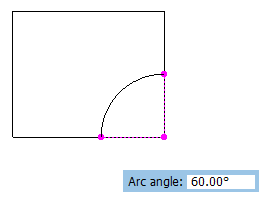
You want to draw a rectangular table top for a computer desk with a rounding where the person sits in one corner. The dimensions of the table are 1,200 x 1,000 mm. The rounding is 500 mm from the corner of the table.
Follow the instructions below:
Draw a rectangle with the dimensions 1,200 x 1,000.
Select the Arc through radius and angle component and click it in position the corner of the rectangle, where you are to cut out a piece to create the rounding.
In the input display, enter 500 mm in the field Radius.
Snap one of the arc's fixing points on one of the sides of the rectangle (if it has not already snapped there) and click it in position.
Choose the direction of the arc using the mouse and click.
Drag the arc out to 90 degrees and click it in position (see Figure 4).
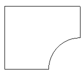
Remove the corner piece using the Trim line tool.
 |
 |
| Figure 4 | Figure 5 |
The Arc through three points component is used when three fixing points are given.
Example:
You want to draw a curved bay, which is 2,000 mm wide and 1,000 mm deep.
Follow the instructions below:
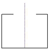
The drawing layout looks like in Figure 6. There is a space left for the bay.
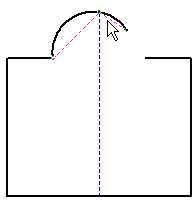
In order for there to be three points for the arc to snap to, you must create the middle point using a Help line.
Select the Help line.
Move it towards the middle of the solid line on the lower long side. The help line will find the middle of the long side of its own accord. The text Middle is displayed.
Click the help line in position, continue to hold down the mouse button and drag the help line to the desired length (Figure 7).
Select the Arc through three points and snap it to the first point. Click the arc in position.
Move the mouse pointer to the middle point, which is the end of the help line. The arc snaps. Click the arc in position (Figure 8).
Move the mouse pointer to the last fixing point and do a final click.
 |
 |
 |
| Figure 6 | Figure 7 | Figure 8 |