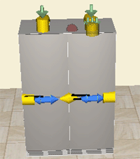

When selecting a component in CET Designer by clicking it, different symbols will become visible in 2D and in 3D. When you look at a selected component in the program's 3D view, you will see that more icons are shown than in 2D view. Each symbol has a unique function or purpose.
Snap points
In 2D the snap point are shown as yellow squares (see Figure 1) and in 3D as yellow cylinders (Figure 2) that identify that the component is selected, but not connected to another component. However, the snap points indicate where the component could connect to other components. When clicking and dragging a snap point, it also allow you to stretch the component.

Figure 1

Figure 2
Yellow triangles
Indicate that two components are connected or snapped together. When you click a triangle, the components disconnect from one another.
Green arrow
Are shown together with the yellow snap points to indicate the direction in which the selected component will be stretched.
Three green arrows
Are shown together with the yellow snap points to indicate the direction in which a whole group of connected components will be stretched simultaneously.
Blue arrows
Show that you can change the hinge side for a cabinet, for example. Simply click one of the blue arrows.