Before you start making a drawing, it is a good idea to pre-set known values. You do this in the Defaults dialog, accessed by clicking on the Defaults button at the top of the Line Drawing tabs. These settings will only apply to components which have not yet been positioned in the drawing area. Click here for more information on modifying components after they have been positioned.
The Defaults dialog is accessed both from Line Drawing 1 and Line Drawing 2. The dialog has three main tabs: General, Surface and Dimension. At the bottom of the dialog is a Reset to Default Values button where at any stage, you can reset the dialog to the default values.
On the General tab, you pre-set values for lines, arcs, circles, ellipses and rectangles. It contains the following fields:
In the 3D field, in the Height box, you enter the height of the component, which you are about to draw (e.g. a wall) when you view it in 3D. Using Distance to floor, you can set the distance between the floor and the bottom edge of the component.
In the Simple Lines field you can choose the Line type of the lines in the drawing. In the same field, in the Width drop-down list, you can enter the width of the lines. There are seven thicknesses between one pixel and 1 mm. The standard width is 0,18 mm.
Under Double Lines, in the Thickness box, you enter the distance between double lines.
If you would like drawing aids to appear on the printout, check the box Show drawing aids on printout in the Printout field.
On the Surface tab, you pre-set values for the Surface component. It contains the following fields:
In the 3D field, in the Thickness box, you enter the height of the surface when you view it in 3D, i.e. its thickness. Using Distance to floor, you can specify how high the surface is above the floor. The value you enter is the distance between the floor and the underside of the surface.
From the drop-down list under Lines you can choose the Line type of the lines which surround the surface.
Limitations refers to the color filling of the surface. In the Limitations field you can choose one of the following options:
Line drawing components only
Line drawing and house components only
All components
Example:
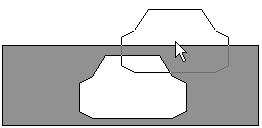
You have drawn a rectangle and positioned an accessory (smaller than the rectangle - in this case a TV) within it. The option All components has been set as the default for the surface. You have then applied a surface in the rectangle. If you now move the TV, there will be a "hole" in the surface, corresponding to the shape of the TV (see Figure 1). In order to avoid this from happening, choose Line drawing components only in the Limitations field before applying the surface.

Figure 1
The Color button at the bottom of the Surface tab allows you to pre-set a different default color for the surface than the predefined dark grey.
In order to change the default surface color, proceed as follows:
Click on the Color button.
The Material/Color Change dialog is displayed.
In the drop-down list next to Surface Name, check that Top face is selected.
Under Color Model/Type, select RGB Color. The RGB Color field is then activated.
In the drop-down list, choose a color.
Click on OK or Apply.
Back in the Defaults dialog, click on OK or Apply.
Go to the bottom of the Line Drawing 2 in order to see the new default surface color on the component tab.
On the Dimension tab, you pre-set the properties for dimensions. It contains the following fields:
Under Text, in the Size box, you pre-set the size of the dimension text. If you want the dimension unit displayed on the drawing area, select the first checkbox, Show unit. Select the second box, Use horizontal text on vertical dimensions, if this is a desired default option for your dimensions. Select the third box, Use vertical text on horizontal dimensions, if this is a desired default option for your dimensions.
The Graphics field contain the following settings:
Distance - pre-set the distance between the dimension line and the line you want to dimension.
Gap - pre-set the size of the gap between the adjacent dimension lines and the line (wall etc.) you are dimensioning.
Arrow type - select the desired default arrow type for your dimensions.
Line width - select the desired default line width for your dimensions.
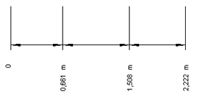
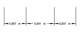
In the Continuous field it is possible to pre-determine what information you would like the Continuous Dimension to display after placement in the drawing area. Leaving the Show chain dimension box empty will only display the vertical accumulative dimensions when placing the continuous dimension in the drawing area (see Figure 1). If you instead uncheck the box Show accumulative dimension, only the horizontal chain dimensions will appear (see Figure 2).

Figure 1

Figure 2
When you have made the desired changes, always confirm with OK or Apply.