The settings that you make in the Control Panel are saved, so you only need to do them once.
If you want to open the Control Panel dialog, follow the instructions below:
Click on File in the menu bar.
From the File menu, choose Control Panel. The Control Panel dialog is displayed.
|
Note:
|
The Control Panel has four main tabs:
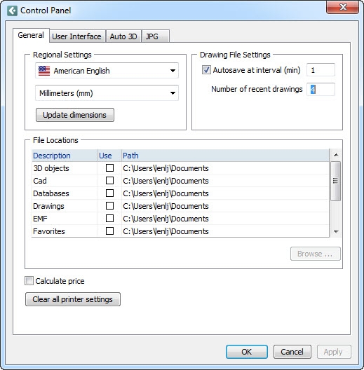
The General tab in the Control Panel contains two main fields: Regional Settings and Drawing File Settings.
Click here to view the General tab.
In the Regional Settings field, the desired language and unit are chosen in the two drop-down lists in the top left-hand corner of the dialog.
Clicking the Update dimensions button will automatically change the dimension unit on dimensions that have already been placed in the drawing area.
|
Note:
|
In the Drawing File Settings field there is checkbox called Auto save at interval. Using this function means that your work is saved at regular intervals. You can choose not to auto save your work (however, we recommend that you do), by unchecking the box Auto save at interval. If you choose to auto save at interval, you can choose how often your work should be saved (every 1 to 60 minutes). Only the 10 most recent versions of your drawing(-s) will be saved.
In the text field next to Number of recent drawings you decide how many of your recently opened files you want displayed when clicking on Recent Drawings in the File menu. The minimum number is 1 and the maximum is 12.
In the File Locations field (see Figure 1 below) you can define paths to many of the different types of files that are opened and saved during your work in the program. The different file alternatives are: 3D objects, images, Cad drawings, databases, EMF files, favorites, drawings, textures and VRML files.
In order to define new paths to one of the alternatives above, proceed as follows:
Select the desired alternative by clicking on it, for example the Images option, to determine where all the 3D images that you create should be saved.
Click the Browse button and define the desired path.
In the Use column, make sure that the box is checked.
Figure 1
If you check the Calculate price box (we recommend that you do), the price of the component(-s) that you position on the drawing area will be displayed. The price information is shown in the status bar in the bottom left-hand corner of the Configura window. If you do not want to display price information, uncheck the box Calculate price.
Activating the price information will also enable the Calculation dialog to be updated automatically when you keep it open and add components to the drawing area.
When you click on the Clear all printer settings button, you delete all printer settings in the program. This applies to settings for Print Frame, Print Drawing and Print List.
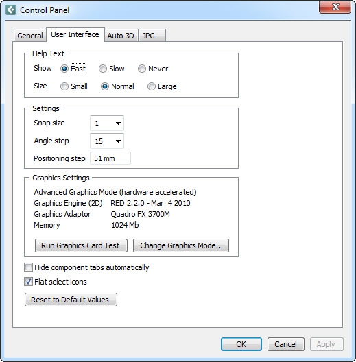
The User Interface tab in the Control Panel contains two main fields: Help Text and Settings.
Click here to see the User Interface tab.
Help text is displayed in a light yellow box (Figure 2) when you move the mouse pointer over a component. It contains information about the current component, for example its dimensions. Using the different radio buttons, you can choose whether you want help text to appear when you move the mouse pointer over a component, and if you do, how quickly it should be displayed. If you choose Fast, the help text is displayed immediately. If you choose Slow, the text is displayed after a delay of a few seconds. Choose the option Never, if you do not want the help text to be displayed at all. You can also choose whether the help text should be Small, Normal or Large.
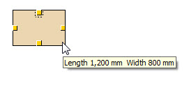
Figure 2
In the Settings field, you can change the Snap size. "Snap" refers to snap points, which are the yellow triangles or squares which appear on a component when it is activated. You can choose between eight different sizes for the snap points. The smallest size is ½ and the largest is 3.
Angle step is the size of the angle step a component takes when you drag to rotate it. Select the desired value in degrees.
Positioning step is the size of the step a component takes when you move it in the drawing area by means of the arrows on the keyboard. Select the desired value in millimeters.
Checking the box Hide component tabs automatically, you can make the drawing area larger. The gray component tabs on the left-hand side of the drawing area disappears to the left. However, it will re-appear temporarily if you move the mouse pointer to the tab row.
Unchecking the Flat select icons box, will allow you to go back to the old program icons, i.e. to when their appearance on the tabs was slightly raised and more "button-like".
At the bottom of the dialog is a Reset to Default Values button where at any stage, you can reset the settings on the tab to the default values.
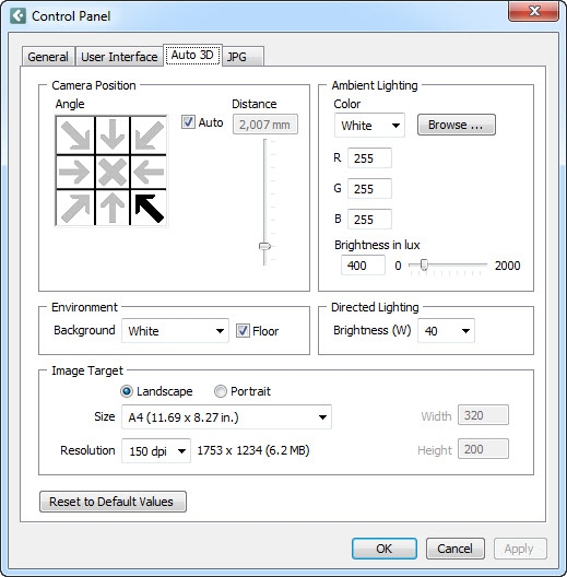
The Auto 3D tab contains settings for the two automatic cameras on the toolbar. Accordingly, what you pre-set here will only affect images that are generated automatically in the program, using the two buttons Auto 3D (Fast) and Auto 3D (Detailed).
Click here to see the Auto 3D tab.
The Auto 3D tab in the Control Panel contains four main fields: Camera Position, Ambient Lighting, Environment, Directed Lighting and Image Target.
In the Camera Position field you use the arrows to select the angle from which you want the automatic photographs to be taken. If, for example, you want to take a picture from the top right corner of the drawing area, choose the arrow in the top right corner. To take a picture from above, choose the cross in the center.
The Auto box is checked by default. This means that the camera-distance calculations are automated. Unchecking the box will allow you to set the camera distance for all angles manually. The text field and the slider bar are then activated. Under the Distance heading, choose the desired distance between the camera and the object you are about to take a picture of, by dragging the slider bar or typing the distance in the text field.
In the drop-down list under the Color heading you can choose your preferred color for the ambient lighting. There is a choice of white, red, green, blue or yellow light. You can also define your own RGB Color by choosing Custom in the list. The Browse button opens the Select and Edit RGB Color dialog. Here you can easily mix your own RGB colors and create a database containing them.
To, for example, use yellow ambient lighting instead of the default white one, follow these steps:
Under the heading Color, click the arrow to expand the drop-down list.
Choose Yellow.
Click on OK or Apply.
Click on one of the Auto 3D options on the toolbar, in order to see the result.
Using the Brightness in lux slider bar, you can set the brightness the surrounding light that Configura automatically adds when developing a 3D picture.
|
Note:
|
In the Environment field, you can select the background of the pictures taken by the automatic cameras. This is done in the drop-down list next to Background.
You can also choose whether the developed picture should have a floor or not by ticking the Floor checkbox.
In pictures developed using one of the two automatic cameras, besides the ambient lighting, a spotlight is also automatically inserted in the background. The spotlight is directed towards the object. In the Directed Lighting field, in the drop-down list next to Brightness (W), you can select how strong you want the light from the spotlight to be in watt).
In the Image Target field you can make different settings for the image that are about to be rendered. You have three different options:
Orientation: Choose the orientation of the image that are about to be rendered; landscape or portrait.
Size: Specify the size of the image by selecting one of the options in the Size drop-down menu, or enter the exact size (in pixels) in the input fields to the right.
Resolution: You also have the possibility to change the resolution of the image by selecting one of the options in the Resolution drop-down menu. The resolution concerns the quality of the image; the higher resolution, the better quality of the rendered image.
At the bottom of the dialog is a Reset to Default Values button where at any stage, you can reset the settings on the tab to the default values.
|
Note:
|
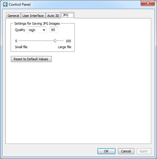
Before saving pictures in JPG format you should consider what level of quality is required, i.e. what compression rate to use. On the JPG tab under Settings for Saving JPG Images you can choose the size – and hence quality – of the pictures you save in the JPG format in the program. If you choose maximum quality (100) you will get quite a large file. If you choose 50 you will get a smaller file of somewhat lower quality.
Click here to see the JPG tab.
There are four ways to choose quality:
Next to Quality, select one of the four alternatives Low, Medium, High and Max in the drop-down list.
Enter your preferred value, between 1 and 100.
Drag the slider bar that runs between 1 and 100.
If you want to return to the program's default settings, click the Return to Default Values button.
Click here to read more about settings concerning picture quality.
|
Note: JPG is a so-called destructive format. This means that the smaller your JPG file, the lower the quality of your compressed picture. |
For all settings in the Control Panel, always click OK or Apply when you have made the desired changes.