
In the Render & camera settings dialog, you control the camera position and the contents of an image.
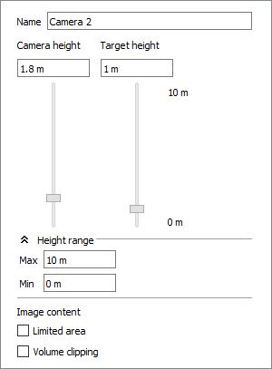
At the top of the Camera settings you will see the name of the camera that is currently selected in the drawing. Verify that it is the correct camera before you start changing the settings.
Just below are two sliders that enable you to adjust the position of the camera - Camera height and Target height. These two settings together determine the vertical angle of the camera.
Using the Camera height slider, you can set the height of the camera. When you open the Render & camera settings dialog, the default setting is 1.80 m. This could represent a person of normal height taking a picture. By dragging the Camera height slider, or by entering the height you want in the text box, you can set the height of the camera anywhere between 0 and 2.7 m.
Using the Target height slider, you can specify the height of the camera's focus. For example, if you are photographing a table, the appropriate target height is around 1 m..
You can also access these settings by pressing down the Ctrl key while dragging the camera's yellow snap points.
|
Below the Camera height and Target height settings, you will find a Height range section. If you want to change the maximum and/or minimum height for the camera and target, enter the desired values in the respective fields. The min and max values are also shown to the right of the Camera height and Target height sliders. The Height range section can be expanded or collapsed by clicking the arrows to the left of the title.
It can be difficult to position the camera correctly and produce a good image in a small space. Using either Limited area or Volume clipping in the Image Content section, you can leave out the walls and other components that you do not want in your picture.
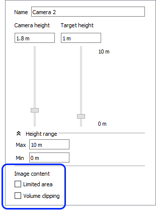
If the checkbox Limited area is selected, a rectangular stretchable area is created in the drawing area. Everything within this area will appear in the developed image. Even if only part of a component, for example the corner of a table, is in the limited area, the whole table will appear on the image.
If you want to use the Limited area option, follow these steps:
Select the camera from the Tools tab. Position the camera in the drawing area and aim it by dragging the target to the area or the object which you want to photograph.
Double-click anywhere on the camera, except on the snap points. The Render & camera settings dialog opens.
In the Camera settings section, check the Limited area option. A rectangle with dashed lines and yellow snap points appears. The rectangle with the dashed lines is the limited area.
The components and the environment in the limited area now appear in the Live View. Rendering an image now will only include the limited area in the rendering.
Note:
|
You can stretch, shrink, move and rotate the limited area. You can also move the target within the limited area.
To do this, follow the instructions below:
To stretch or shrink the limited area, click on one of the snap points on the side of the rectangle, hold down the mouse button and drag the area in the direction you want.
To rotate the limited area, click on one of the snap points on the corner of the rectangle, hold down the mouse button and drag the area in the direction you want it to move.
You can move the whole limited area by clicking on the activated target and dragging it in the direction in which you want the area to move to. The camera will follow.
You can also move the focus point within the limited area. To do this, follow the instructions below:
Deactivate the target's snap point by clicking on it. The snap point will change color to gray.
Put the cursor on the deactivated snap point, and click and hold the mouse button.
Drag the target to the position within the limited area where you want it to be.
Using Volume clipping, you can create a restricted area within the wide angle (only the components within this area will appear in the developed image. This means that only that part of a component which is inside the volume clipping area will be visible.
If you want to use the Volume clipping option, follow these steps:
Select the camera from the Tools tab. Position the camera in the drawing area and aim it by dragging the target to the area or the object which you want to photograph.
Double-click anywhere on the camera, except on the snap points. The Render & camera settings dialog is displayed.
In the Camera settings section, check the Volume clipping option. The volume clipping area appears as two dashed lines within the camera's wide angle. The snap points on the volume clipping area are gray as default (deactivated).
Drag the lines of the volume clipping area to a position where they enclose the area which you want to appear in the image.
Activate the volume clipping area by clicking on the gray deactivated snap points (snap points will turn yellow to indicate that they are now active).
Click Render to render the image with the current settings.
Note:
|
Regardless of which environment settings you decide to use, you can go into the other settings and tweak them according to your wishes before rendering the image. Follow these links to read more about the options available: Realtime options, Preset, Render quality, Image dimensions, Lighting & Shadows, and Environment.